PLANNED · Design and measurement preparation
Direct-to-Chip Cooling Bench.
A planned experiment connecting fixture design, instrumentation, and thermal analysis.
- Engineering question
- How does coolant flow affect the installed source-to-coolant thermal response?
- My contribution
- Fixture planning, instrument choices, measurement definitions and a repeatable procedure, with AI-assisted software preparation.
- Current evidence
- PLANNED bench, analytical planning and synthetic offline checks. No qualified thermal dataset yet.
- Next step
- Review the fixture and measurement setup, then commission and collect qualified records.
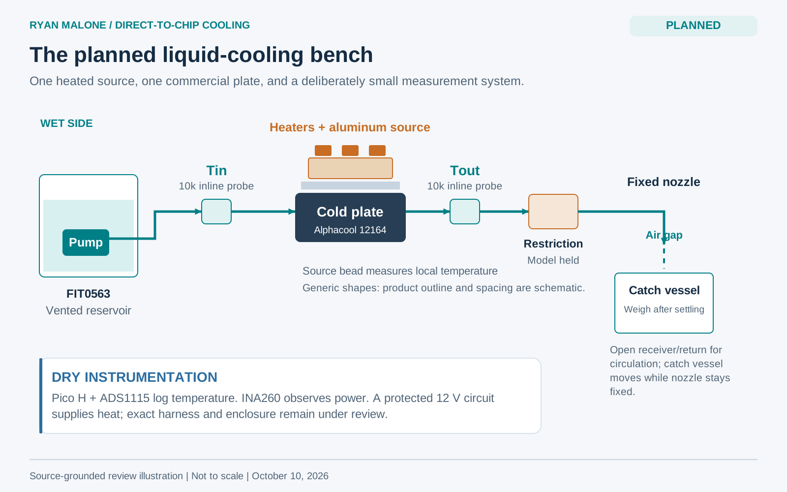
My role and engineering question
I am planning an independent experiment to ask: how does coolant flow change the installed source-to-coolant thermal response? My focus is the fixture, instrument choices, measurement definitions and a repeatable test procedure. The cold plate is a commercial component; the source and mounting fixture are proposed parts of the experiment.
Preparation so far
Project records include analytical heat/flow planning, draft fixture layouts, a component/interface inventory and measurement procedures. Codex-assisted acquisition and analysis software has recorded offline checks using simulated inputs. These records support preparation; hardware commissioning, calibrated sensing and the first qualified thermal dataset remain next steps.
First experiment
At one fixed qualified heater pattern, compare three qualified flow conditions and independently re-establish one same-mount repeat. The first deliverable is a traceable dataset and an uncertainty-supported interpretation of installed thermal response. A second heater pattern and a full remount belong to the later campaign.
What I plan to measure
Associate the temperature, electrical-input and catch records with the same accepted measurement interval. Preserve raw data, calibration/configuration records, units and uncertainty.
- Temperatures: coolant inlet and outlet, plus one embedded source sensor. The source reading is local, not chip-junction, plate-face or hottest-point temperature.
- Heater input: actual terminal voltage × current, measured separately from coolant heat pickup.
- Water flow: catch mass divided by collection time; derive volumetric flow using the stated water density.
- Energy check: Q̇water = ṁ cp (Tout − Tin). Interpret signed disagreement with electrical input in terms of uncertainty, heat losses, storage and inlet drift.
- Installed thermal response: retain the source location, coolant-temperature reference and heat-rate denominator used in the analysis.
Fixture design decisions
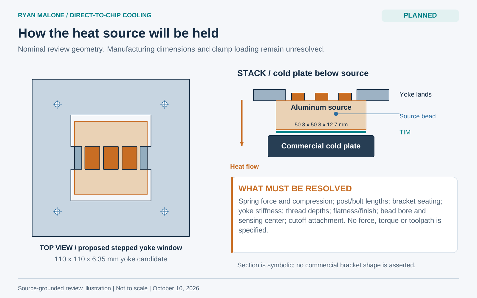
The proposed aluminum source transfers heat through a thermal interface material to the commercial cold plate. A stepped yoke is intended to hold the assembly. Clamp loading, bracket seating, post/fastener dimensions, flatness and sensor installation still need review and received-part measurements. The illustration below explains the candidate geometry; it is not accepted native CAD.
Build and qualification milestones
Each step depends on the relevant reviews, resources and preceding evidence.
- Resolve requirements and inspect exact received parts, mating dimensions and available instruments.
- Complete native fixture drawings and loading requirements; fabricate under appropriate supervision and inspect the parts.
- With heat disconnected, qualify plumbing, sensing, real logging and reviewed protection; calibrate the complete temperature chains.
- After the required reviews, run attended commissioning and check installed thermal behavior.
- Collect the three-flow campaign and independent same-mount repeat; preserve raw records, estimate uncertainty and explain the supported finding.
Later extensions
The broader bench would add a second heater pattern, complete remounts and hydraulic characterization. Pressure-loss testing, a separate air-cooled fixture and an observational AI predictor remain later options. The predictor would not control the heater or replace independent protection.
Current status and next step
The heated bench remains planned; no qualified thermal-performance dataset is presented. The next useful evidence is a reviewed fixture and measurement setup, followed by real commissioning and calibrated records. The component choices below are candidates, not evidence of purchased, assembled or compatible hardware.
Evidence and methods
Planned component choices
Candidate identities from the project records. Reservoir selection, interfaces and received variants remain unresolved; this is not a released purchase or assembly list.
| Subsystem | Candidate | Purpose |
|---|---|---|
| Cold plate | Alphacool 12164 | Transfer heat from the proposed source to water. |
| Circulation | DFRobot FIT0563; vented reservoir still unselected | Supply the proposed water path. |
| Temperature sensing | Two inline 10k coolant sensors; one dry source thermistor | Observe inlet, outlet and local source temperatures after calibration. |
| Logging | Raspberry Pi Pico H + ADS1115 | Acquire traceable temperature records after real commissioning. |
| Electrical input | INA260 | Observe heater electrical input after terminal-boundary and calibration checks. |
Analytical detail: planning for a measurable temperature signal
This ideal energy-balance calculation screens the expected coolant-temperature rise for instrument and uncertainty planning. It does not demonstrate that actual sensors can resolve the signal.
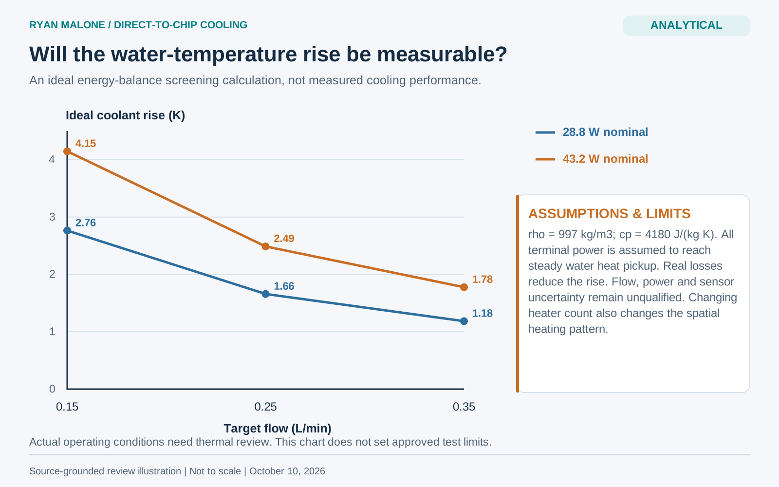
Changing heater count changes spatial heating as well as total power. The first experiment keeps one qualified heater pattern fixed; the second pattern is a later comparison.